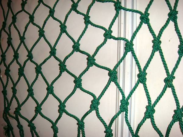


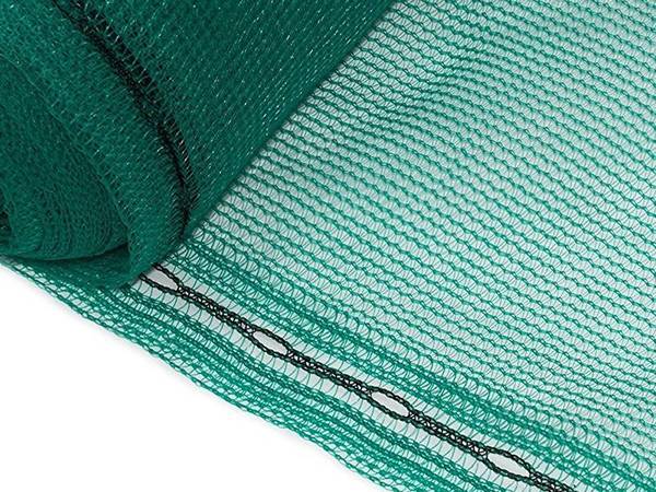
Vertical debris netting for scaffolding systems

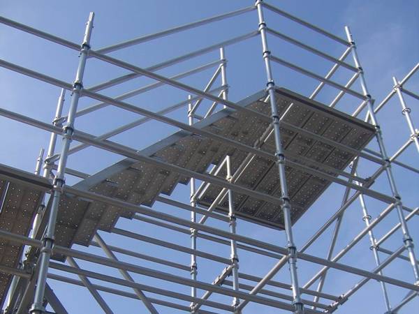
Cuplock scaffolding is a kind of multi-purpose steel tube scaffold system that can be used as load-bearing scaffold and working scaffold.
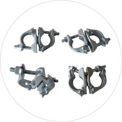
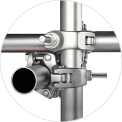
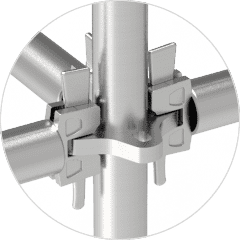
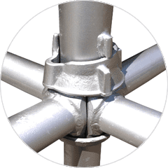
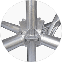
Its unique joint connection allows up to four ledgers to be connected to a standard in one single clamping action without nuts and bolts. The locking device consists of two cups: one is the lower cup welded to the predetermined intervals on the standard member and the other is the sliding upper cup. The ledger forged steel blades are inserted into the lower cup. The upper cup is moved down and rotated to secure ledger forged blades in place by hammering, thereby providing a positive and rigid connection.
It can be flexibly assembled into modular scaffolding, birdcage scaffolding, suspended scaffolding, mobile scaffolding and supported scaffolding. It is widely used in industrial facilities, oil refineries, shipyards, construction sites, temporary stands, etc.
Assemble Process

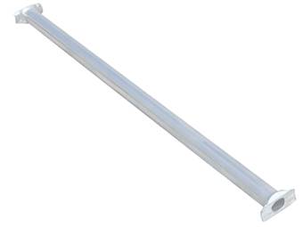
A: Ledger
It refers to the horizontal members of the cuplock scaffolding that are used to provide horizontal support for the load and steel planks. It is welded with two forged blades at both ends of the steel pipe with a diameter of 38.3 mm.
| Item | Effective Length (mm) | Pipe Diameter (mm) | Pipe Wall Thickness (mm) | Weight (kg) | Minimum Tension (MPa) | Yield Limit (MPa) |
|---|---|---|---|---|---|---|
| CLS-L-560 | 560 | 48.3 | 3.25 | 2.4 | 517 | 414 |
| CLS-L-790 | 790 | 48.3 | 3.25 | 3.2 | 517 | 414 |
| CLS-L-920 | 920 | 48.3 | 3.25 | 3.6 | 517 | 414 |
| CLS-L-1070 | 1070 | 48.3 | 3.25 | 4.3 | 517 | 414 |
| CLS-L-1220 | 1220 | 48.3 | 3.25 | 4.8 | 517 | 414 |
| CLS-L-1520 | 1520 | 48.3 | 3.25 | 6.0 | 517 | 414 |
| CLS-L-1820 | 1830 | 48.3 | 3.25 | 7.0 | 517 | 414 |
| CLS-L-2130 | 2130 | 48.3 | 3.25 | 8.1 | 517 | 414 |
| CLS-L-2440 | 2440 | 48.3 | 3.25 | 9.3 | 517 | 414 |
| CLS-L-2740 | 2740 | 48.3 | 3.25 | 10.5 | 517 | 414 |
| CLS-L-3050 | 3050 | 48.3 | 3.25 | 11.5 | 517 | 414 |
| Notes: The sizes in the table are conventional sizes; other sizes are available upon request. |
||||||
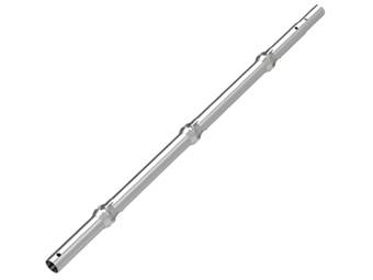
B: Standard
It refers to the vertical members of the cuplock scaffolding system that are used to provide vertical support for the cuplock scaffolding system.
| Item | Effective Length (mm) | Pipe Diameter (mm) | Pipe Wall Thickness (mm) | Weight (kg) | Minimum Tension (MPa) | Yield Limit (MPa) |
|---|---|---|---|---|---|---|
| CLS-S-300 | 300 | 48.3 | 3.25 | 1.9 | 517 | 414 |
| CLS-S-500 | 500 | 48.3 | 3.25 | 3.5 | 517 | 414 |
| CLS-S-1000 | 1000 | 48.3 | 3.25 | 6.2 | 517 | 414 |
| CLS-S-1500 | 1500 | 48.3 | 3.25 | 8.7 | 517 | 414 |
| CLS-S-2000 | 2000 | 48.3 | 3.25 | 11.4 | 517 | 414 |
| CLS-S-2500 | 2500 | 48.3 | 3.25 | 14.2 | 517 | 414 |
| CLS-S-3000 | 3000 | 48.3 | 3.25 | 16.5 | 517 | 414 |
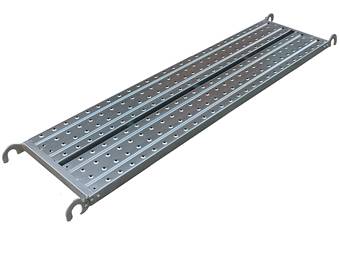
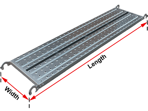
C: Steel Plank
It is a very important part of the cuplock scaffolding system. It is fixed on the cuplock scaffolding ledger for workers to walk on. Every corner is provided with a welded hook. Two or three beams are welded under the scaffold plank. Perforated plates are used to improve its anti-slip performance.
| Item | Length (mm) | Width (mm) | Thickness (mm) | Hook Diameter (mm) |
|---|---|---|---|---|
| CLS-SP-1500 | 1500 | 240, 420, 500 | 1.2, 1.5 | 43, 50 |
| CLS-SP-1800 | 1800 | 240, 420, 500 | 1.2, 1.5 | 43, 50 |
| CLS-SP-1530 | 1530 | 240, 420, 500 | 1.2, 1.5 | 43, 50 |
| CLS-SP-2400 | 2400 | 240, 420, 500 | 1.2, 1.5 | 43, 50 |
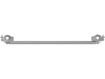
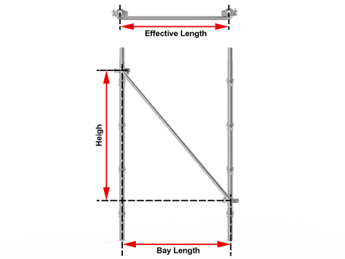
D1: Diagonal Brace with Couplers
It is used to connect two adjacent cuplock scaffold standards at different horizontal lines via couplers at both ends, thereby forming a triangle with the standard and the ledger and providing a more stable cuplock scaffolding system based on the theory of triangular stability.
Coupler is provided at both ends of the diagonal brace and is connected to the standards firmly.
| Item | Bay Length (mm) | Effective Length (mm) | Pipe Diameter (mm) | Pipe Wall Thickness (mm) | Weight (kg) | Minimum Tension (MPa) | Yield Limit (MPa) |
|---|---|---|---|---|---|---|---|
| CLS-DBC-920 | 920 | 2200 | 48.3 | 2.5 | 8.2 | 483 | 345 |
| CLS-DBC-1220 | 1220 | 2340 | 48.3 | 2.5 | 8.5 | 483 | 345 |
| CLS-DBC-1520 | 1520 | 2520 | 48.3 | 2.5 | 8.7 | 483 | 345 |
| CLS-DBC-1830 | 1830 | 2710 | 48.3 | 2.5 | 10.0 | 483 | 345 |
| CLS-DBC-2130 | 2130 | 2930 | 48.3 | 2.5 | 10.4 | 483 | 345 |
| CLS-DBC-2440 | 2440 | 3150 | 48.3 | 2.5 | 10.8 | 483 | 345 |
| CLS-DBC-2740 | 2740 | 3400 | 48.3 | 2.5 | 12.2 | 483 | 345 |
| CLS-DBC-3050 | 3050 | 3650 | 48.3 | 2.5 | 12.8 | 483 | 345 |
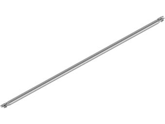
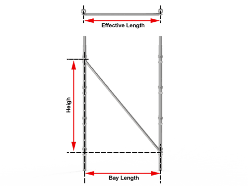
D2: Diagonal Brace with Blades
It is provided with a blade bolted on both ends. Generally, it is connected to the cuplock scaffolding standards by locking blades into the cup lock.
| Item | Bay Length (mm) | Effective Length (mm) | Pipe Diameter (mm) | Pipe Wall Thickness (mm) | Weight (kg) | Minimum Tension (MPa) | Yield Limit (MPa) |
|---|---|---|---|---|---|---|---|
| CLS-DBB-920 | 920 | 2350 | 48.3 | 2.5 | 7.7 | 483 | 345 |
| CLS-DBB-1520 | 1520 | 2520 | 48.3 | 2.5 | 8.1 | 483 | 345 |
| CLS-DBB-1830 | 1830 | 2700 | 48.3 | 2.5 | 9.3 | 483 | 345 |
| CLS-DBB-2130 | 2130 | 2930 | 48.3 | 2.5 | 10.3 | 483 | 345 |
| CLS-DBB-2440 | 2440 | 3150 | 48.3 | 2.5 | 10.6 | 483 | 345 |
| CLS-DBB-2740 | 2740 | 3400 | 48.3 | 2.5 | 11.2 | 483 | 345 |
| CLS-DBB-3050 | 3050 | 3650 | 48.3 | 2.5 | 11.9 | 483 | 345 |
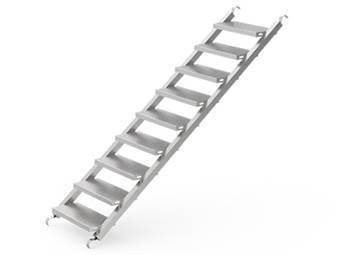
E: Stair Stringer
Stair stringer is fixed on the cuplock scaffolding ledger to provide a ramp for workers to climb up to the upper access. It consists of rectangular steel pipes with hooks and anti-slip stair treads. Diamond-strut anti-slip stair treads are employed to provide superior anti-slip performance and ensure the safety of workers walking on it.
| Item | Length (mm) | Width (mm) | Height (mm) | Hook Diameter (mm) |
|---|---|---|---|---|
| CLS-SS-1800 | 1800 | 550, 860 | 1800, 2000 | 43, 50 |
| CLS-SS-1830 | 1830 | 420, 450, 860 | 1725, 1955 | 43, 50 |
| Notes: All sizes are available upon request. | ||||
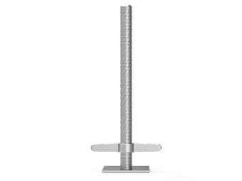
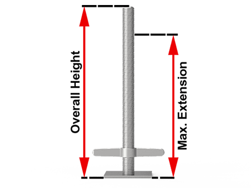
F: Jack Base
It serves as the base of the cuplock scaffolding system. It helps keeping the cuplock scaffolding system stable by adjusting the height of the screw rod.
| Item | Overall Height (mm) | Effective Length (mm) | Base Plate Length (mm) | Base Plate Thickness (mm) |
|---|---|---|---|---|
| CLS-JB-600 | 600 | 460 | 140 | 5 |
| CLS-JB-800 | 800 | 530 | 140 | 5 |
G: Steel Toe Plate
It is a long steel plate set on the standards on both sides of the scaffold plank access. It is almost as high as the instep, therefore, it is called steel toe board. It is mainly used to prevent objects from falling off when they roll to the steel toe board and prevent workers from falling.
| Item | Effective Length (mm) | Height (mm) |
|---|---|---|
| CLS-STB-830 | 830 | 180 |
| CLS-STB-1000 | 1000 | 180 |
| CLS-STB-1140 | 1140 | 180 |
| CLS-STB-1440 | 1440 | 180 |
| CLS-STB-1500 | 1500 | 180 |
| CLS-STB-1750 | 1750 | 180 |
| CLS-STB-2050 | 2050 | 180 |
| CLS-STB-2360 | 2360 | 180 |
| CLS-STB-2500 | 2500 | 180 |
| CLS-STB-2660 | 2660 | 180 |
| CLS-STB-2970 | 2970 | 180 |
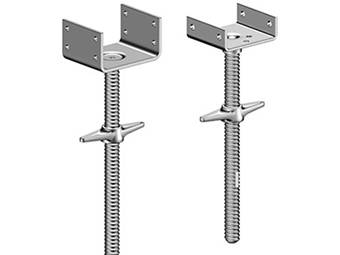
H: U-head Jack
It is mainly used to connect cuplock scaffolding standards to provide strong support for applications where beams are required to be supported. U head is welded on the screw rod with nut, you may screw the nut to adjust the height of the screw rod.It is mainly used to connect cuplock scaffolding standards to provide strong support for applications where beams require support. U head is welded on the screw rod and a nut is provided, you may screw the nut to adjust the height of the screw rod.
| Item | Height (mm) | Screw Diameter (mm) | U-Head Size (L × W × H, mm) | U-head Plate Thickness (mm) |
|---|---|---|---|---|
| CLS-UHJ-600 | 600 | 32, 34, 36, 38 | 160 × 90 × 30 | 5 |
| CLS-UHJ-800 | 800 | 32, 34, 36, 38 | 160 × 90 × 30 | 5 |
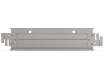
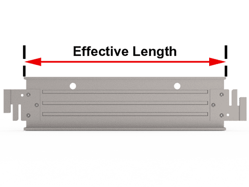
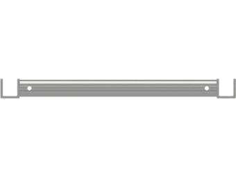
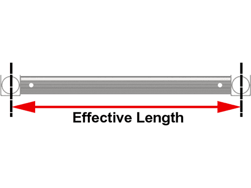
I: Intermediate Transom
It is designed to provide a safe mid-bay support for scaffold boards. One end is provided with an integral locking device to prevent movement along the ledger direction during use.
| Item | Bay Length (mm) | Pipe Diameter (mm) | Pipe Wall Thickness (mm) | Minimum Tension (MPa) | Yield Limit (MPa) |
|---|---|---|---|---|---|
| CLS-IT-790 | 790 | 48.3 | 3.25 | 517 | 414 |
| CLS-IT-920 | 920 | 48.3 | 3.25 | 517 | 414 |
| CLS-IT-1070 | 1070 | 48.3 | 3.25 | 517 | 414 |
| CLS-IT-1220 | 1220 | 48.3 | 3.25 | 517 | 414 |
| CLS-IT-1300 | 1300 | 48.3 | 3.25 | 517 | 414 |
| CLS-IT-1520 | 1520 | 48.3 | 3.25 | 517 | 414 |
| CLS-IT-1820 | 1830 | 48.3 | 3.25 | 517 | 414 |
| CLS-IT-2130 | 2130 | 48.3 | 3.25 | 517 | 414 |
| CLS-IT-2440 | 2440 | 48.3 | 3.25 | 517 | 414 |
| CLS-IT-2500 | 2500 | 48.3 | 3.25 | 517 | 414 |
| CLS-IT-3050 | 3050 | 48.3 | 3.25 | 517 | 414 |
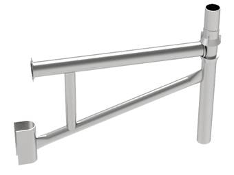
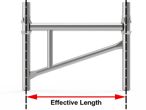
J: Side Bracket
It is an extension of the cuplock scaffolding system that is designed to extend or widen the reach with steel planks put on it. Together with steel planks, it forms a platform that can be used for storing building accessories.
| Item | Effective Length (mm) | Weight (kg) |
|---|---|---|
| CLS-SB-320 | 290 | 1.5 |
| CLS-SB-400 | 570 | 5.4 |
| CLS-SB-610 | 800 | 6.8 |
K: Truss Ledger
It is a horizontal member of ringlock scaffolding that allow for scaffolding over large spans or gaps to provide horizontal support for the load and steel planks.
| Item | Length (mm) | Weight (kg) |
|---|---|---|
| CLS-TL-1000 | 1000 | 4.62 |
| CLS-TL-1500 | 1500 | 6.50 |
| CLS-TL-2000 | 2000 | 8.38 |
| CLS-TL-2500 | 2500 | 10.27 |
| CLS-TL-3000 | 3000 | 12.16 |
Vertical debris netting for scaffolding systems
Horizontal debris netting for scaffolding systems
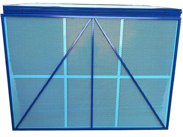
Perimeter safety screen for scaffolds
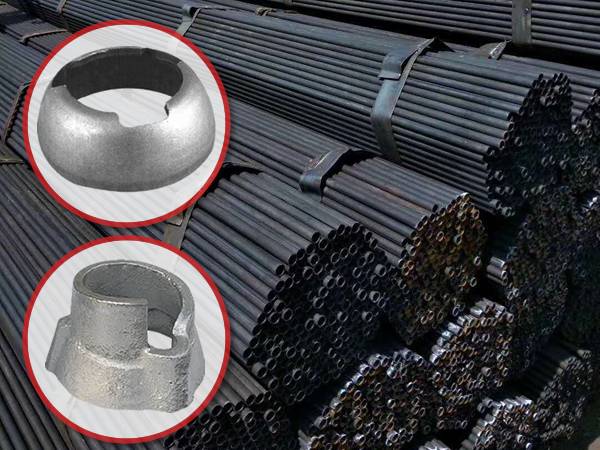
Raw material – steel pipe, lower cup and upper cup
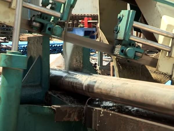
Pipe cutting
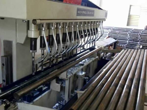
Pipe drilling
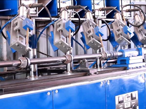
Standard and lower cup welding
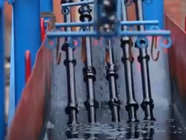
Standard surface treatment
Package & storage
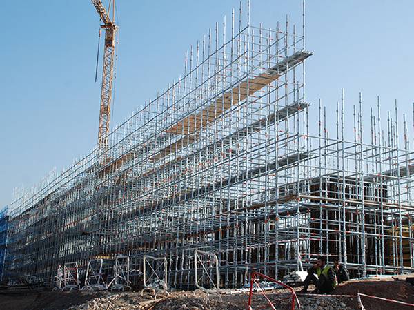
Cuplock scaffolding system
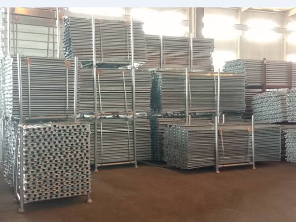
Cuplock scaffolding ledgers in warehouse
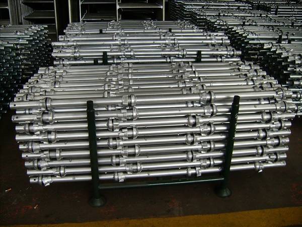
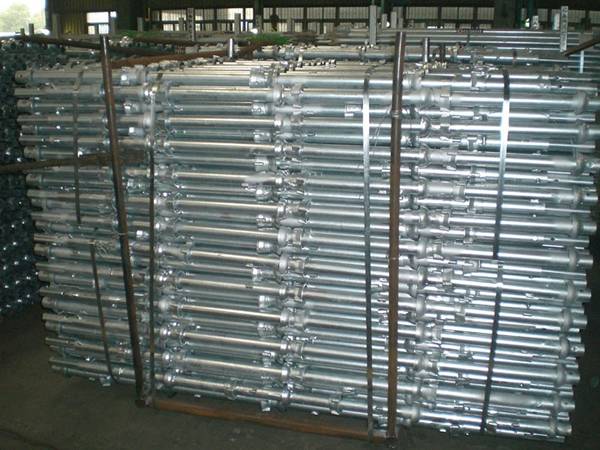
Cuplock scaffolding standards in warehouse
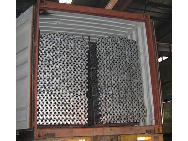
Cuplock scaffold components transportation
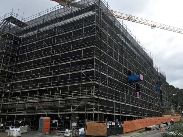
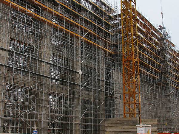
Cuplock scaffold for high-rise construction
Cuplock scaffold for bridge construction
Cuplock scaffold for highway construction